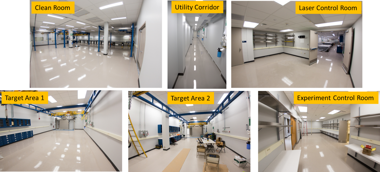
The University of Michigan has funded the expansion of the High Field Science laser laboratories to accommodate the ZEUS facility. The cleanroom (ISO 7) that houses the laser system and laser beam lines has been substantially extended. The building renovation added two new target areas (TA1 and TA2), a new experimental control room, new target preparation facilities and a new laser control room. Below are some photos of the building renovation and the ZEUS facility construction.
Building Renovation
Explore through the photo slideshow below.
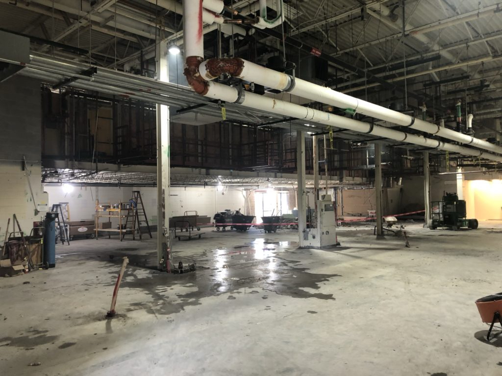
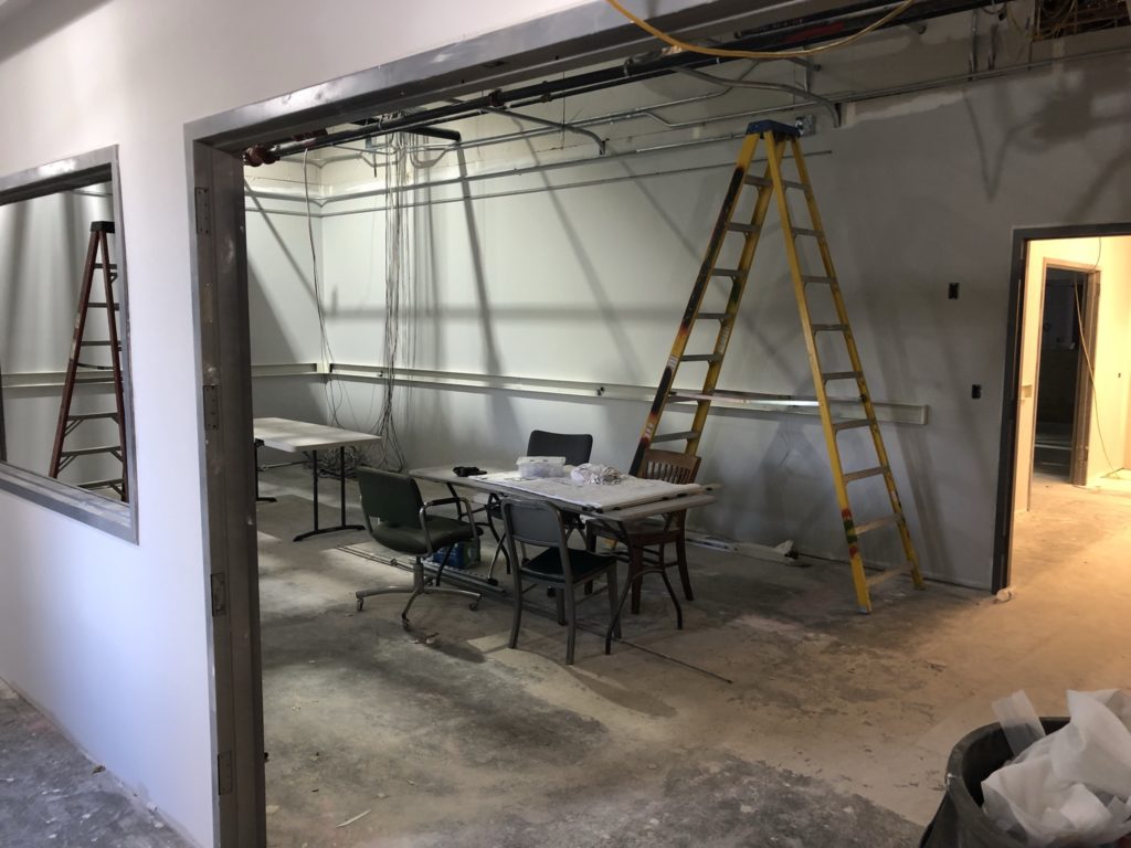
The old laboratories were completely removed to make space for the extended laser clean room, new ZEUS target areas experimental control room and target facilities. (March 2021)
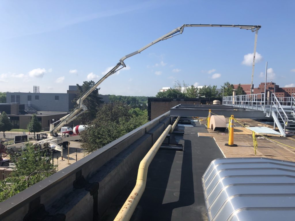
Cement was poured into the building for the thick radiation shielding walls and floor. (May 2021)
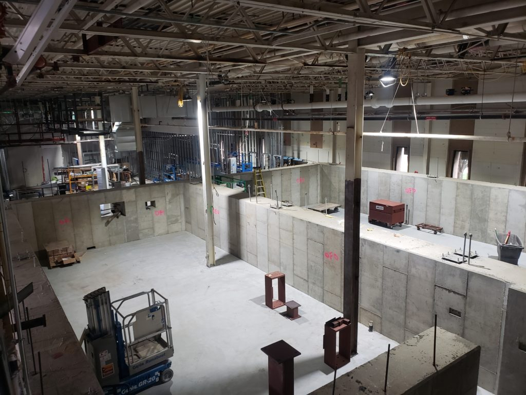
The concrete shielding walls for the new Target Area 1 (right) and Target Area 2 (left) (July 2021).
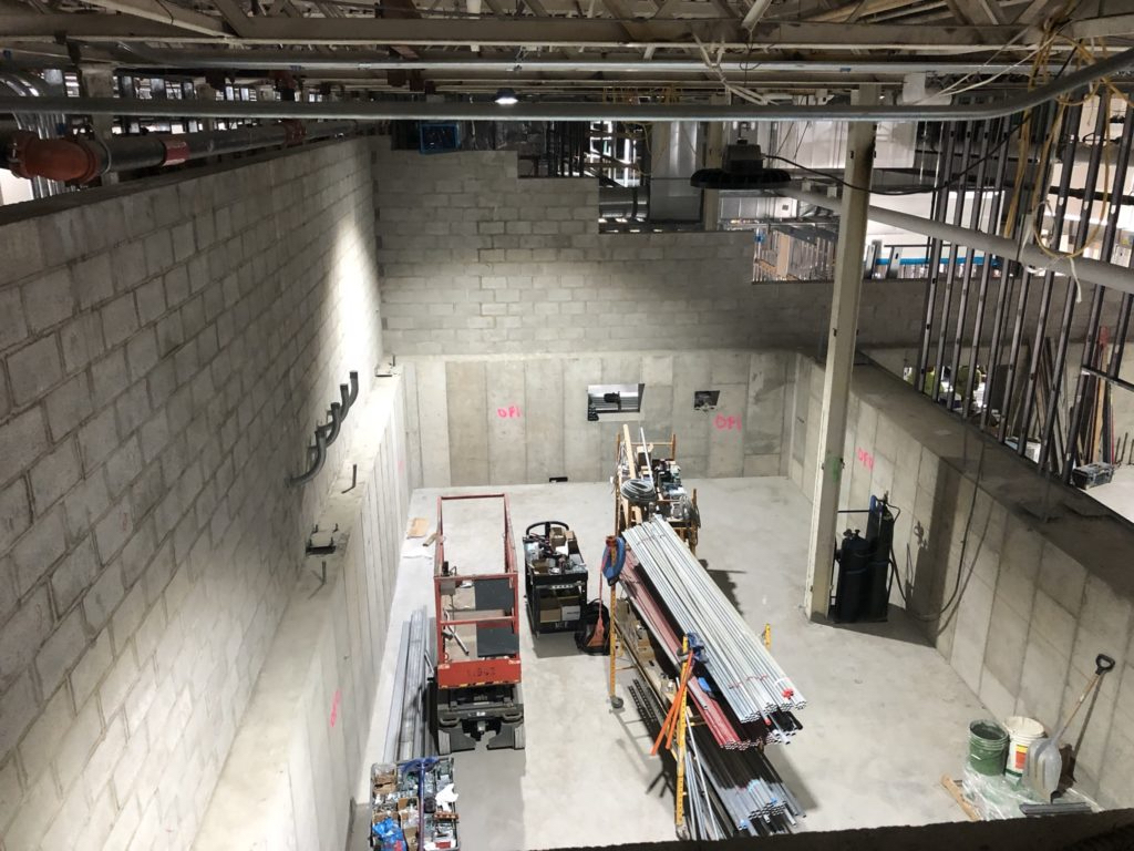
The radiation shielding was extended to the full height of the building to protect the upper level offices. (August 2021)
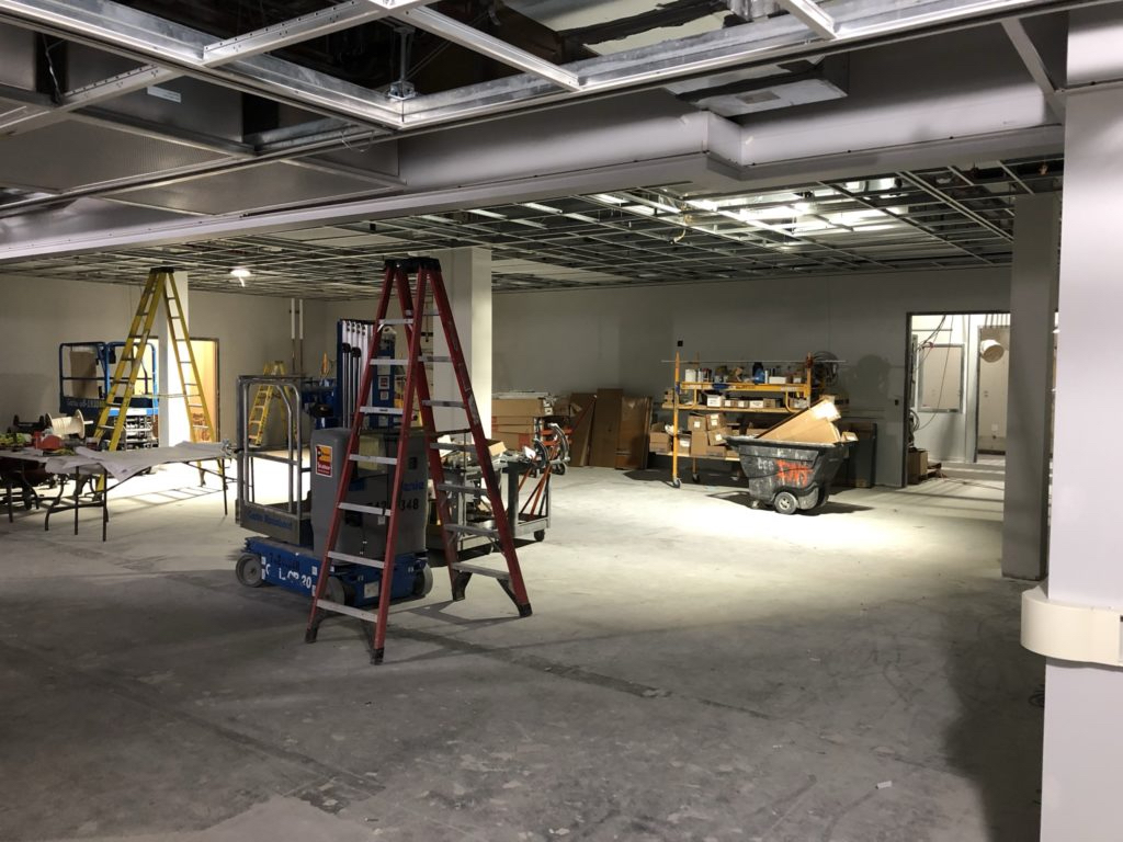
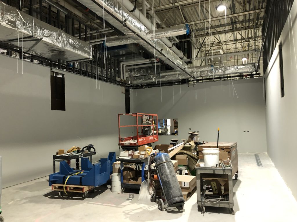
The new laser cleanroom (not yet clean!). (September 2021)
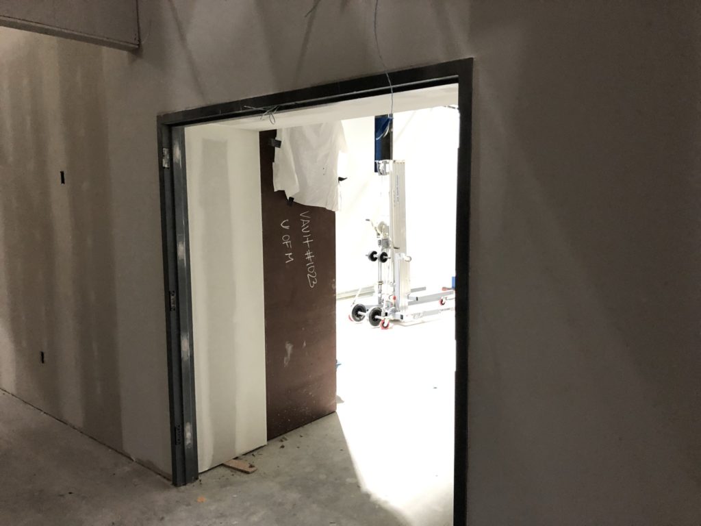
The target areas have thick, rolling shielding doors that close before laser shots. (September 2021)
The new Target Area 1. The window in the shielding wall will allow a long focal length focusing geometry. (September 2021)
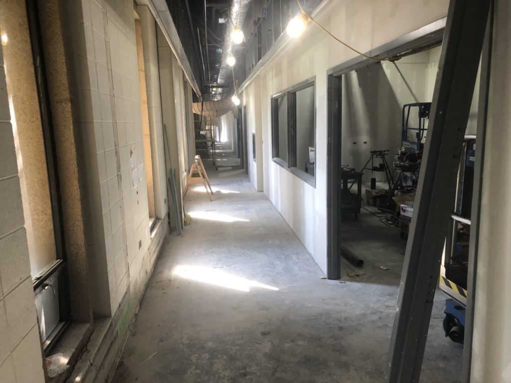
The new corridor running alongside the experimental control room. (October 2021)
The experimental control room – new furniture to come. (October 2021)
The building renovation is completed. (November 18, 2021)
Installation
Explore through the photo slideshow below.
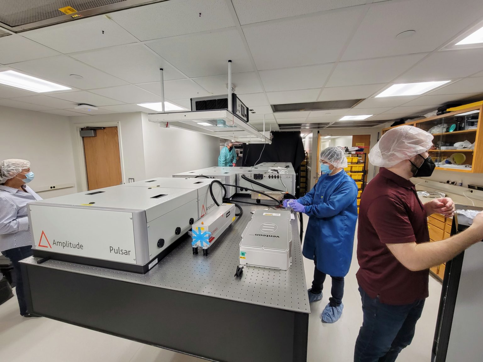
The installation of the Amplitude Pulsar front end. (November 2021)
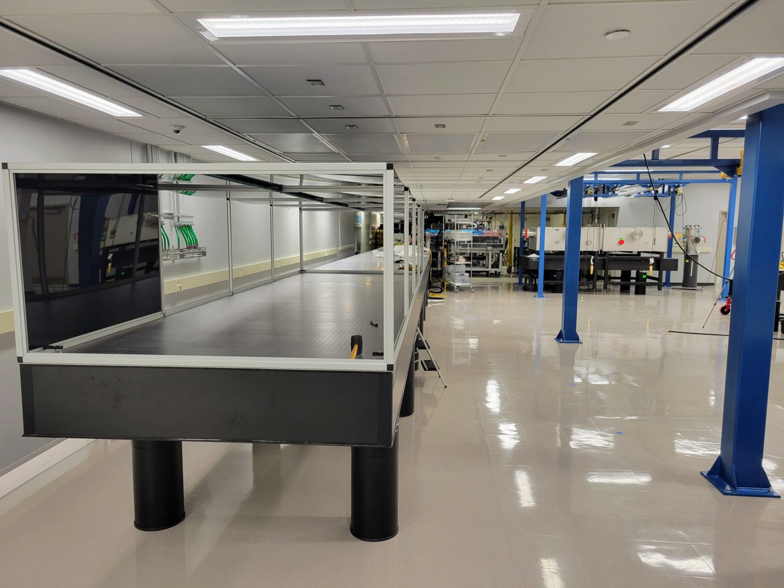
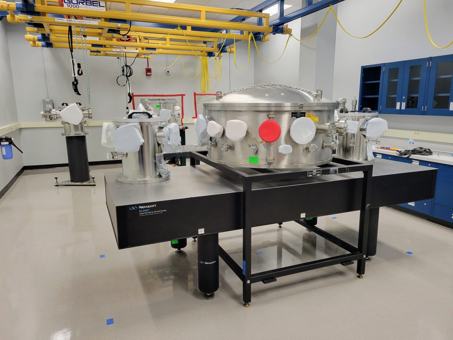
Optical tables for the ZEUS amplifiers installed in a clean room. (November 2021)
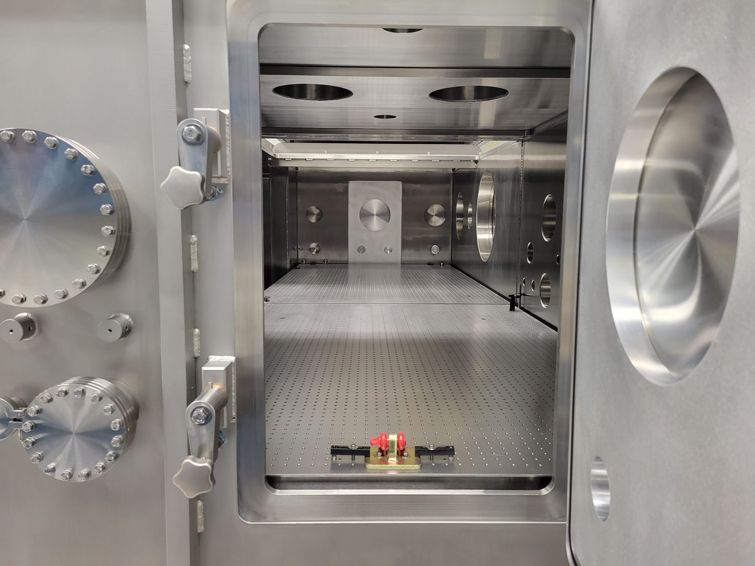
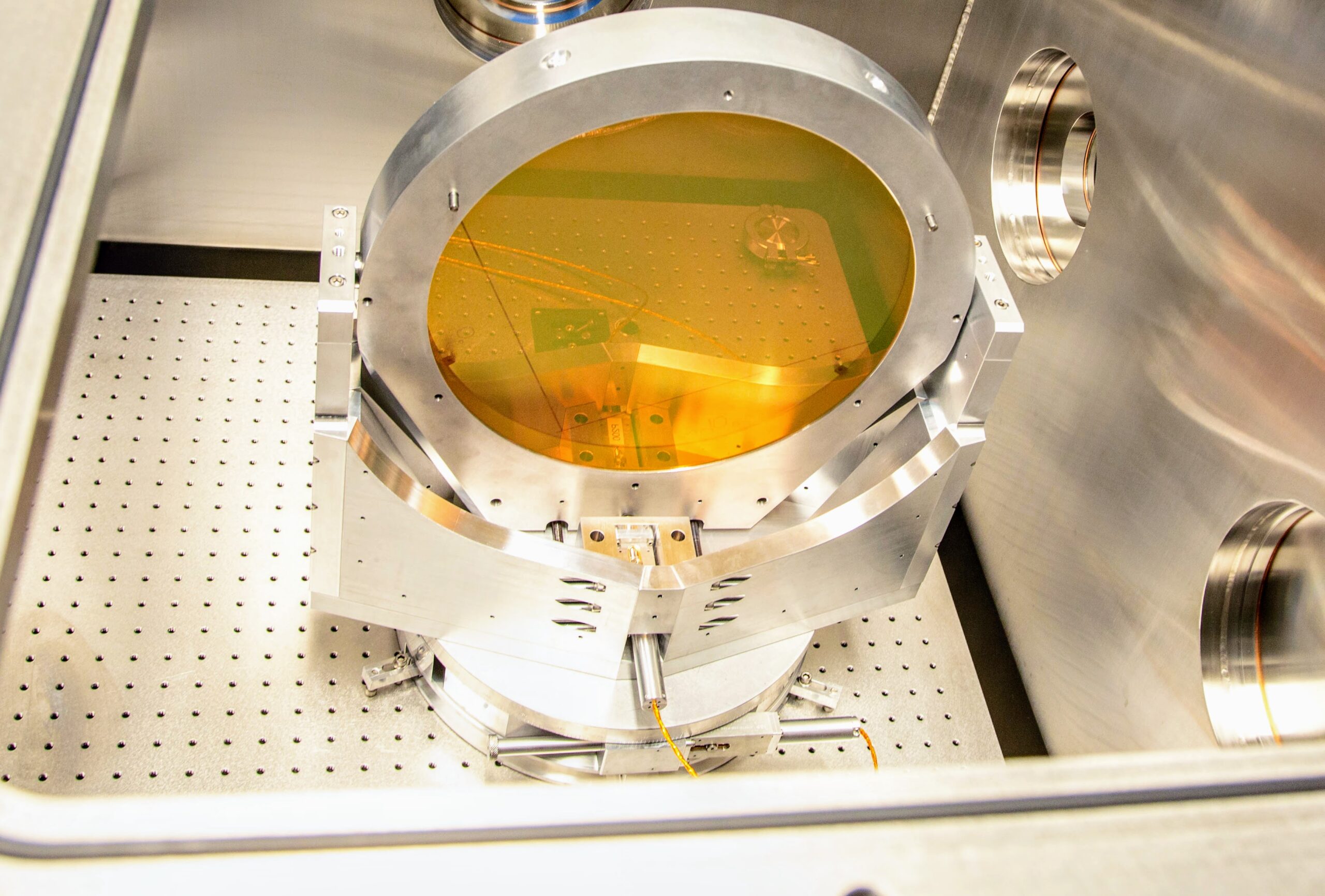
500 TW experimental chamber in Target Area #2. (December 2021)
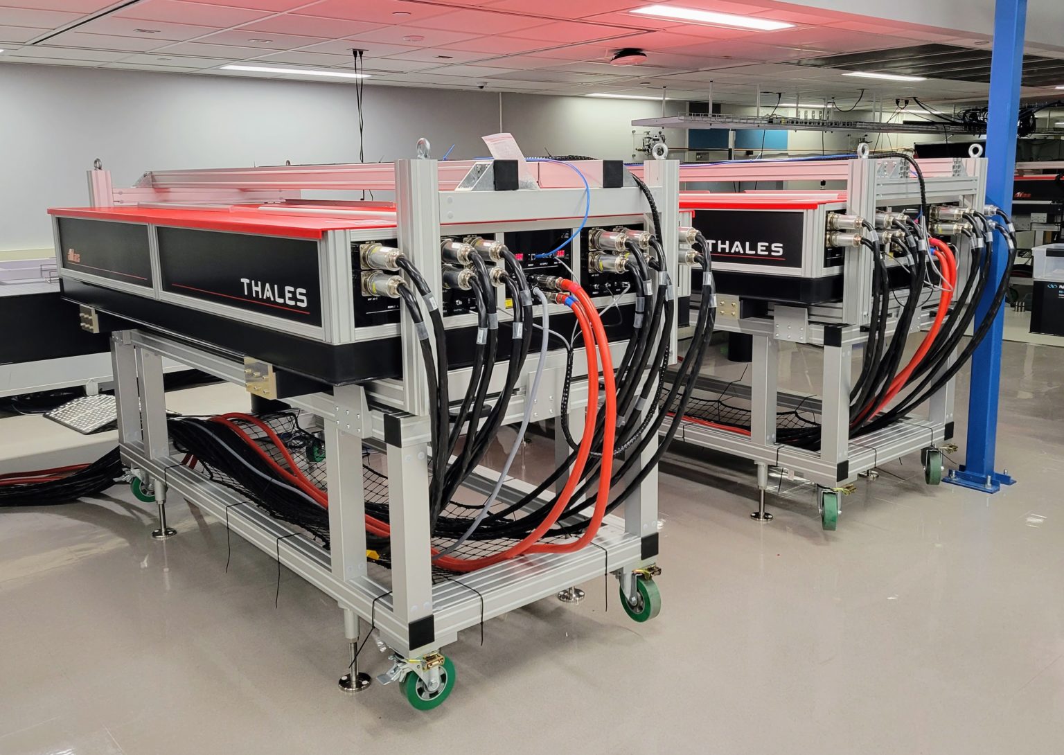
Two ATLAS 100 Nd:glass pump lasers designed to pump the final ZEUS amplifier installed in a clean room. (December 2021)
Clean room with a 500 TW vacuum vessel and beam line going into the ZEUS Target Area #3. (January 2022)
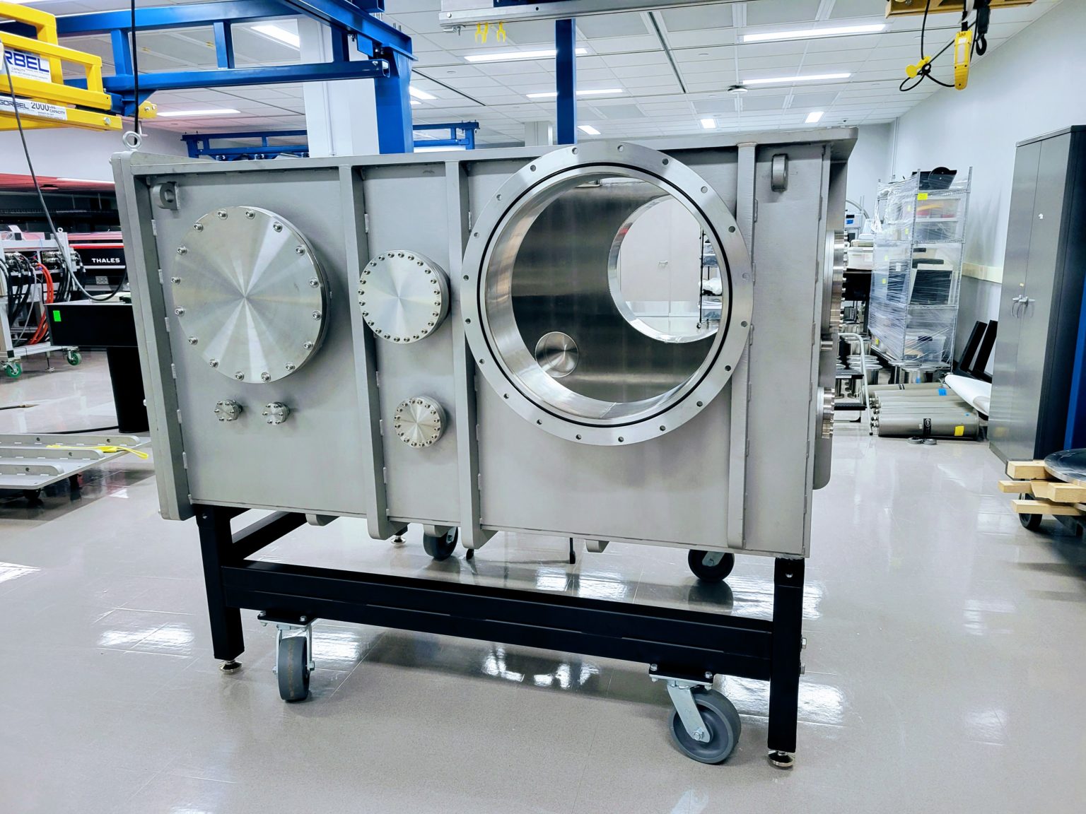
ZEUS switch yard #2 vacuum vessel in the lab. (April 2022)
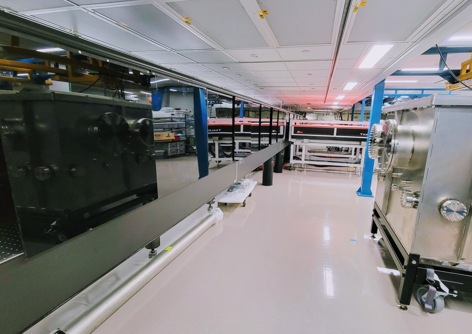
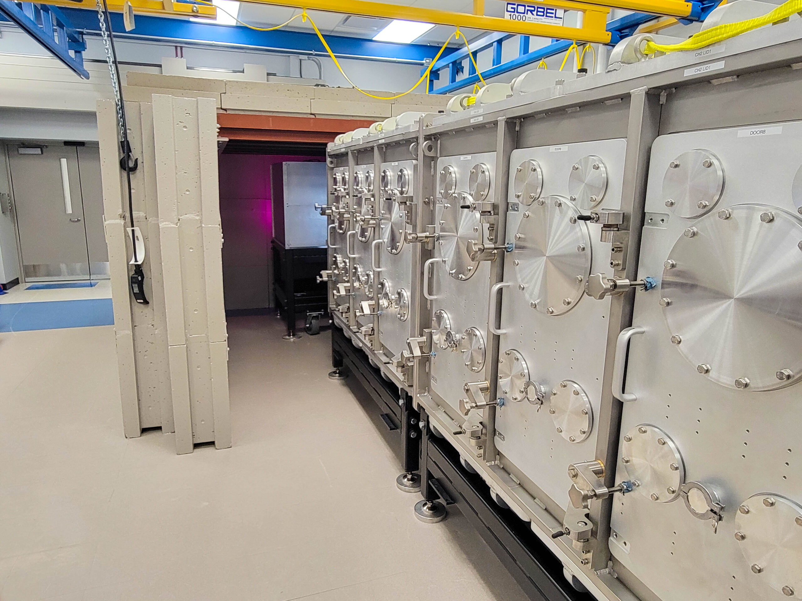
3 PW compressor and switchyard #1 vacuum vessels in the ZEUS facility clean room. (May 2022)
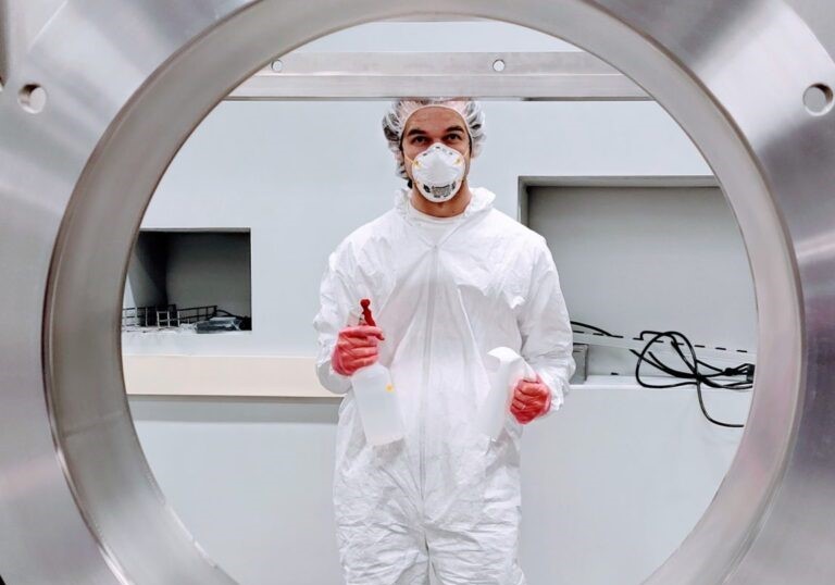
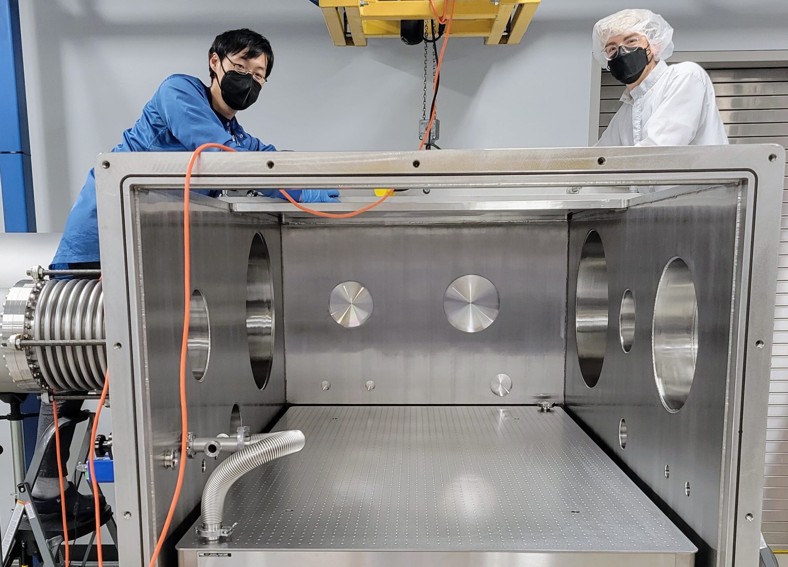
PhD student, Joshua Latham, cleaning the 3 PW compressor and switchyard #1 vacuum vessel. (May 2022)
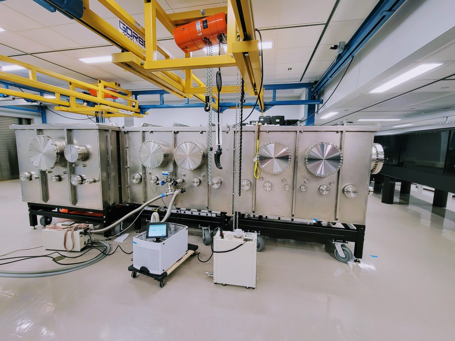
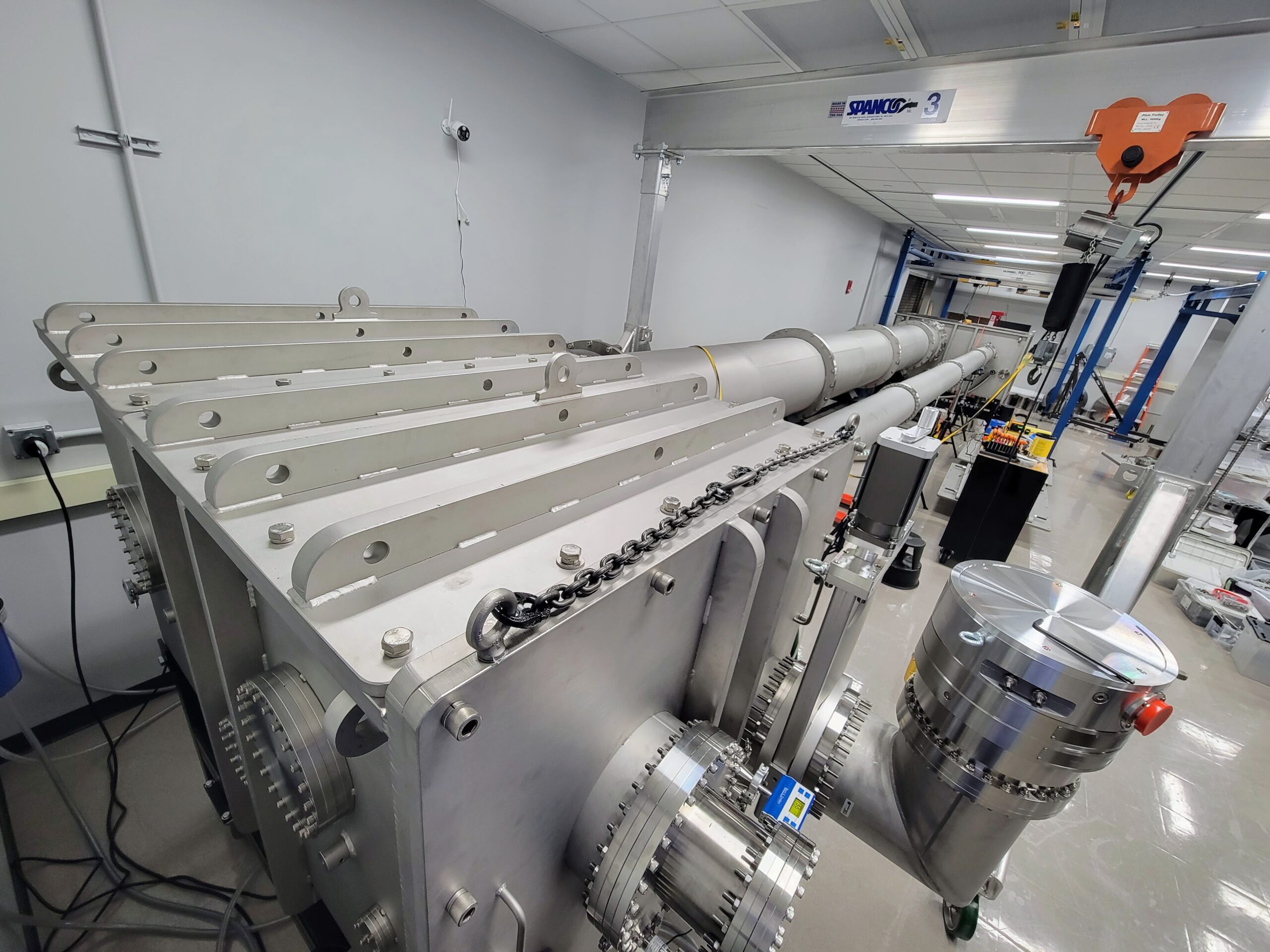
Assembled and vacuum leak tested ZEUS 3 PW compressor and switchyard #1. (June 2022)
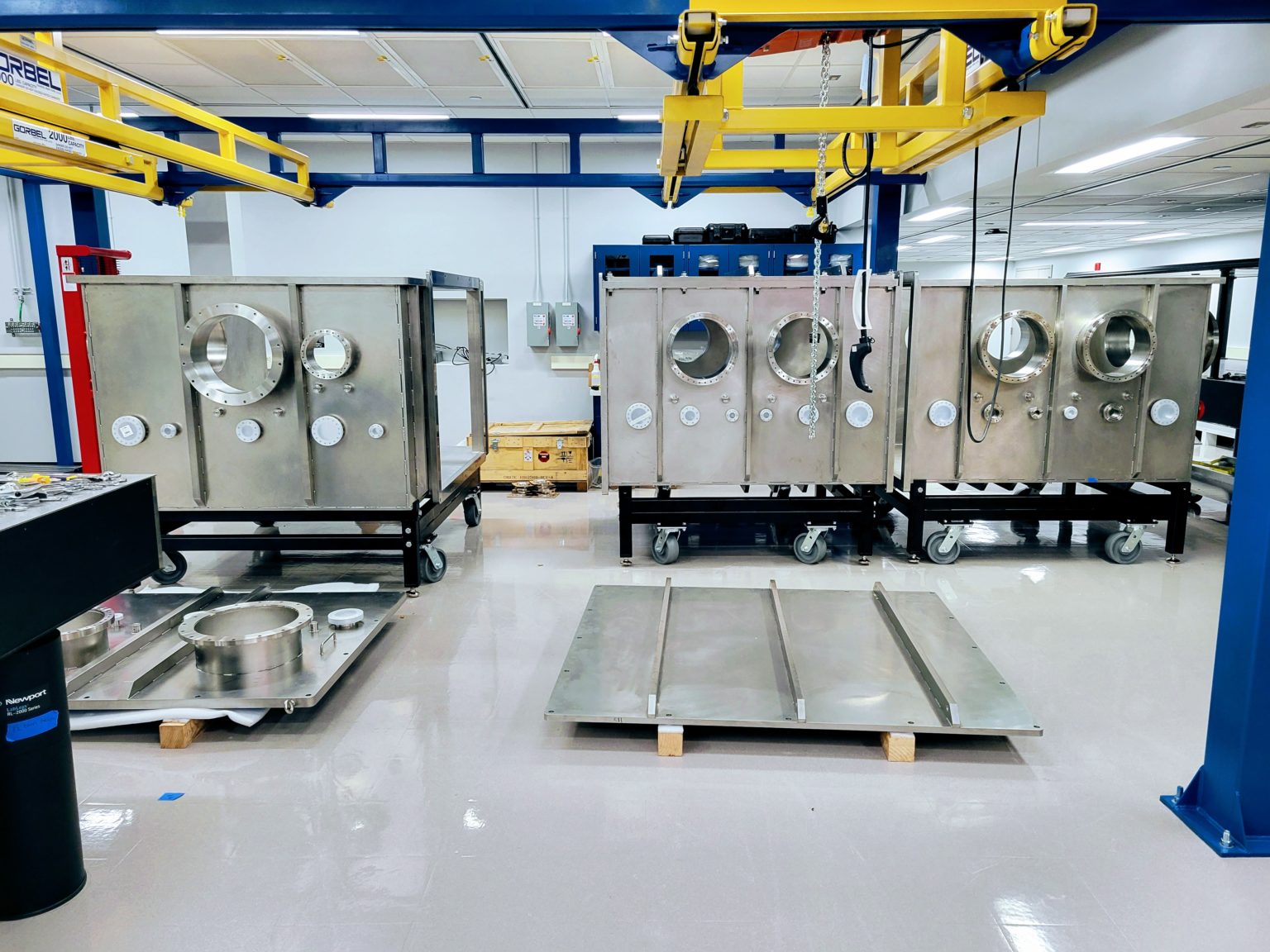
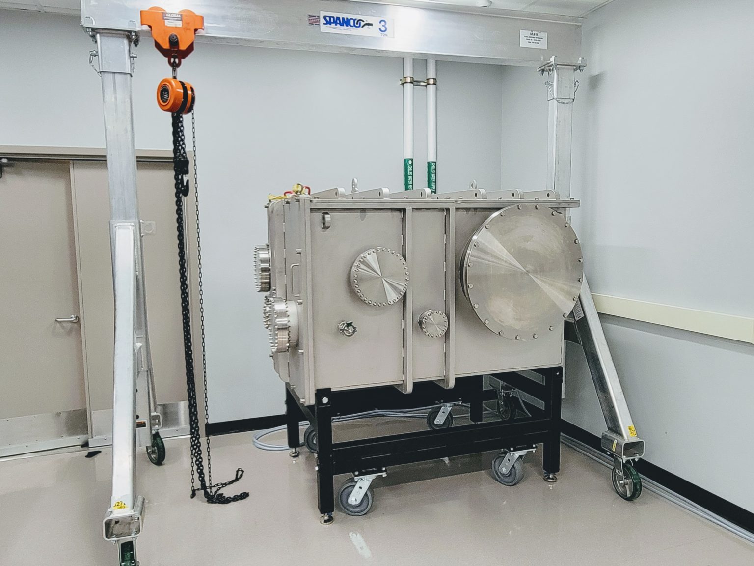
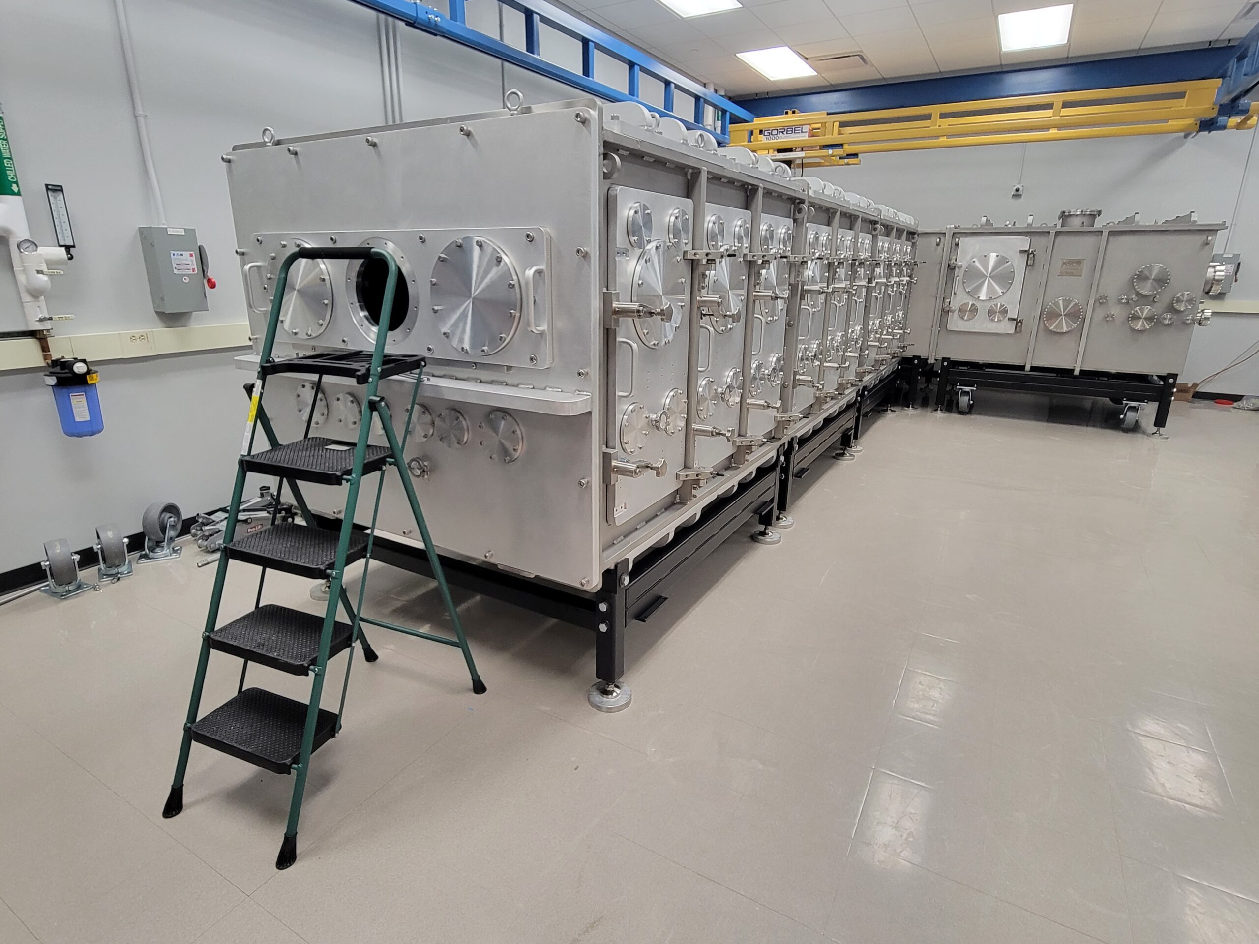
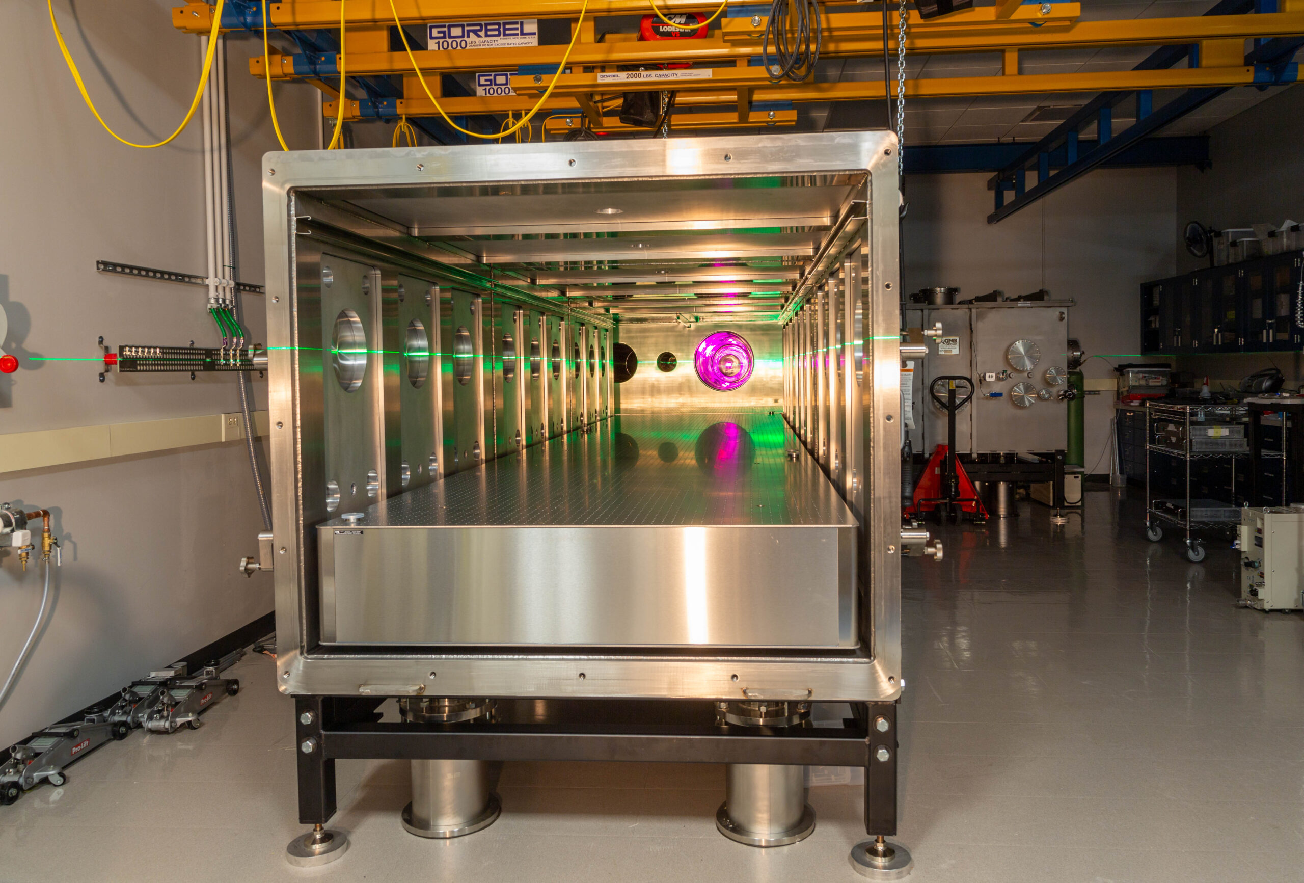
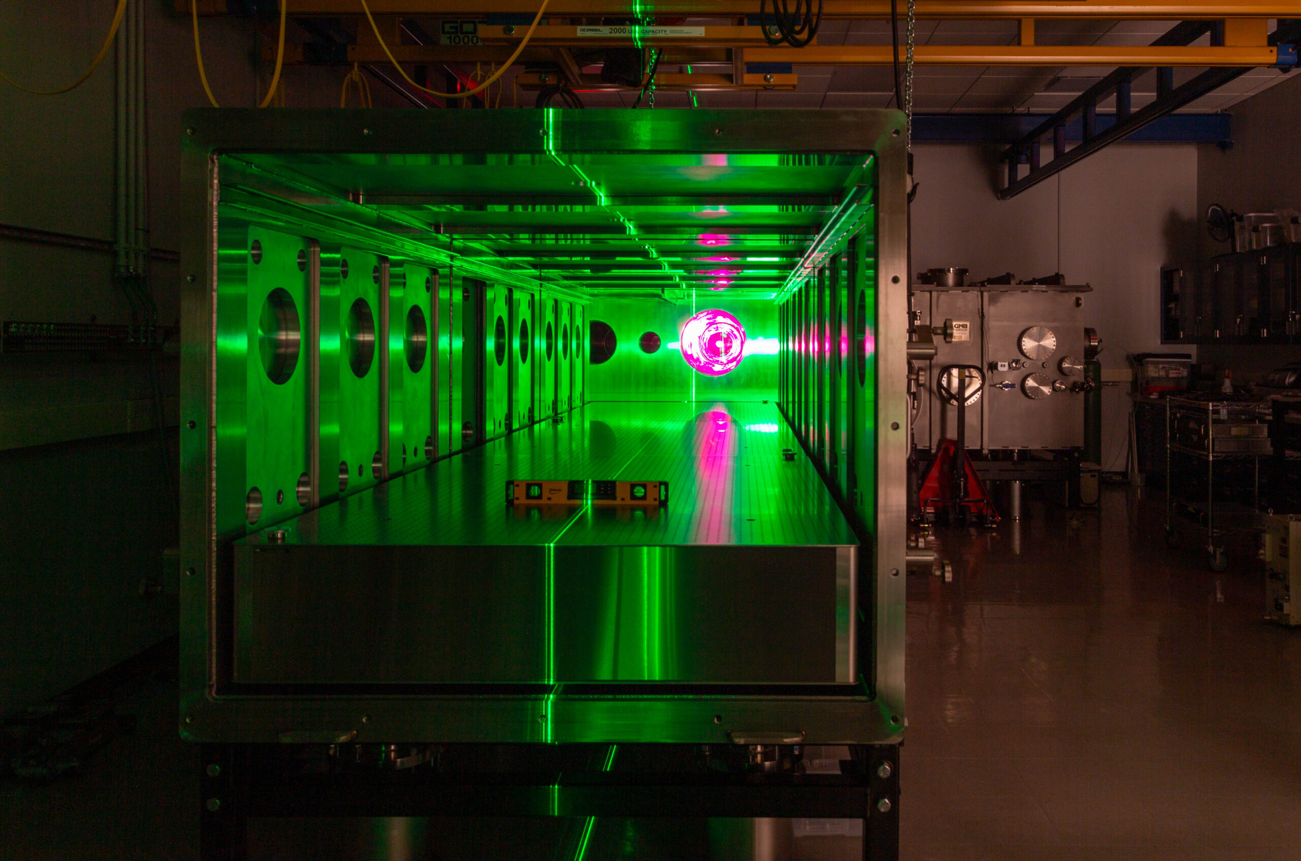
The switchyard #3 vacuum vessels, which holds a long (~20 meters) focusing optics for laser wakefield experiments in the ZEUS facility clean room. (June 2022)
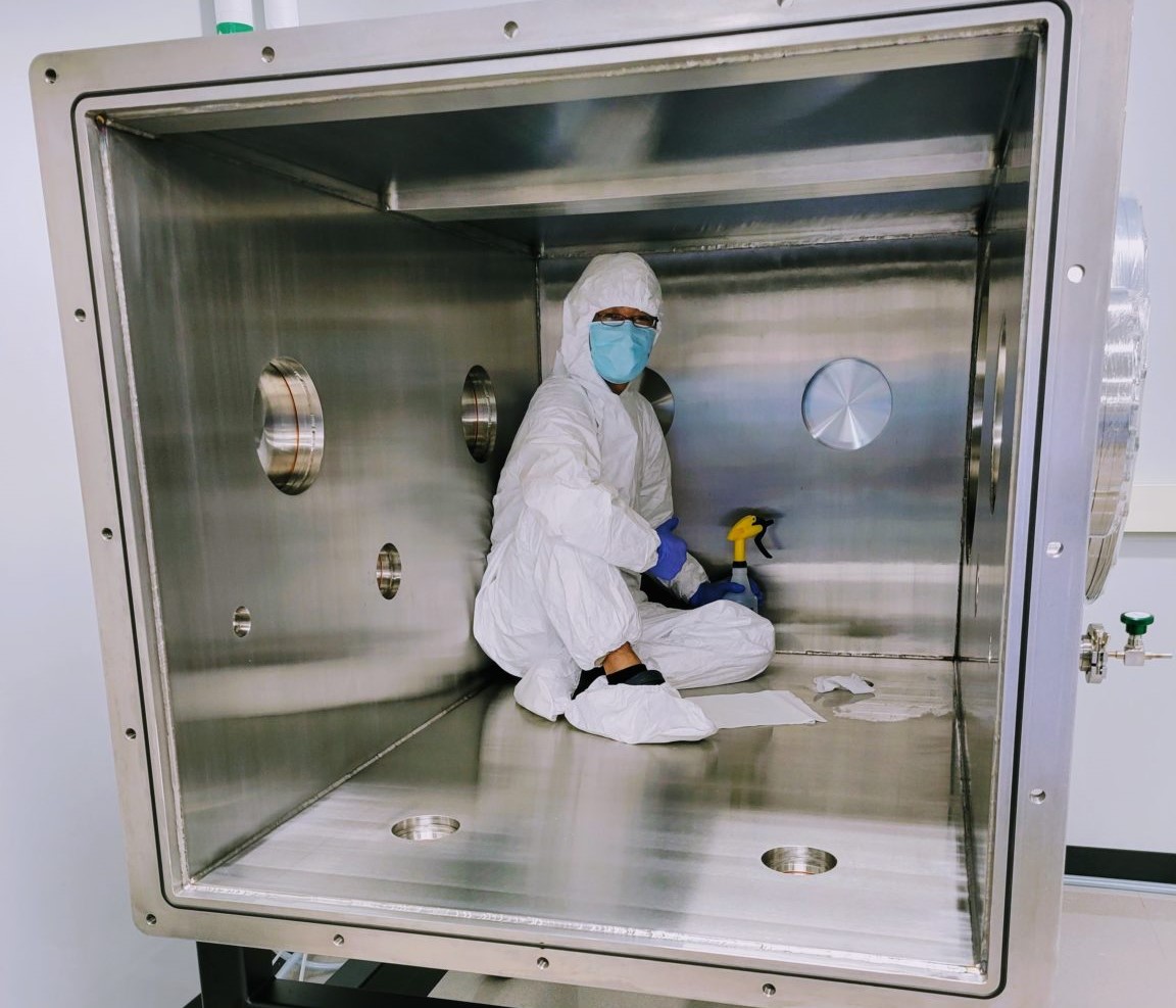
Cleaning of the switchyard #3 vacuum vessels. (July 2022)
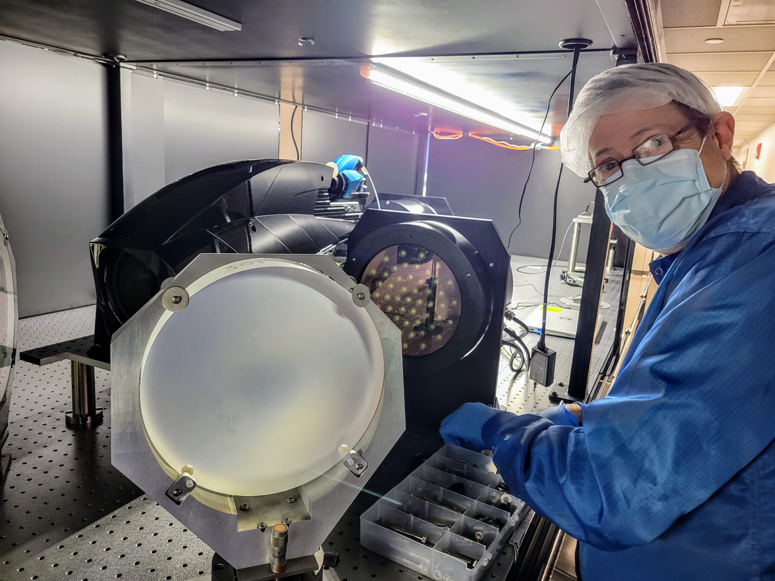
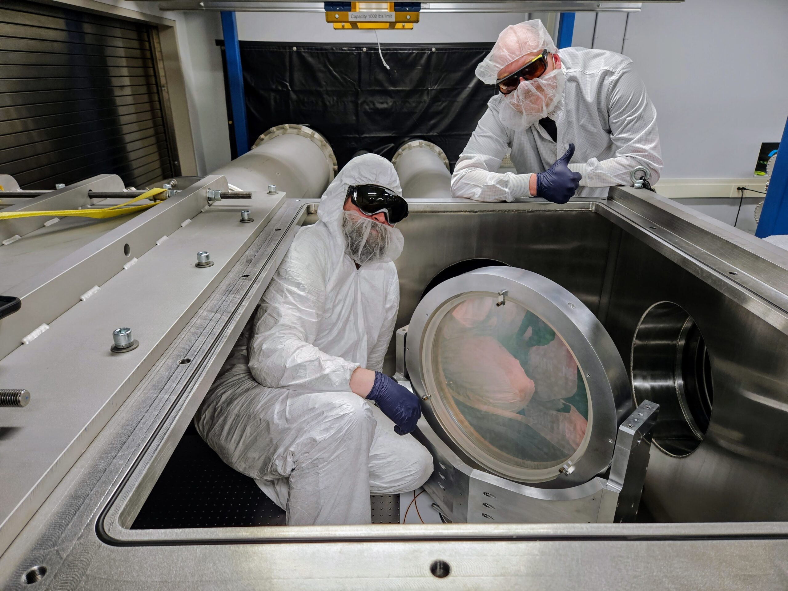
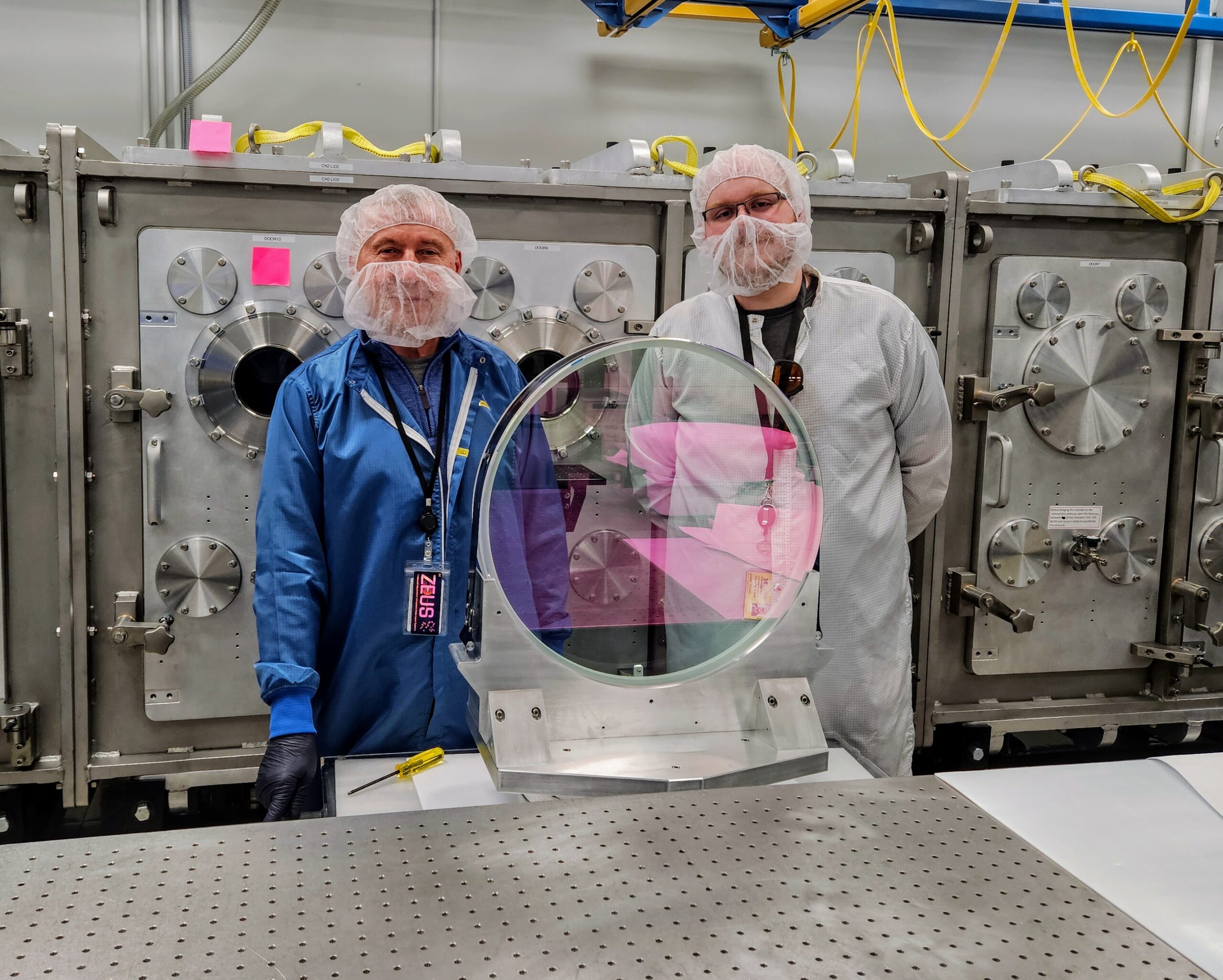
A 12 inch diameter vacuum deformable mirror, controller and wavefront sensor in the ZEUS clean room. (July 2022)
Qualification of the Imagine Optic deformable mirrors (December 2022).
Completion of the switchyard #2 (January 2023).
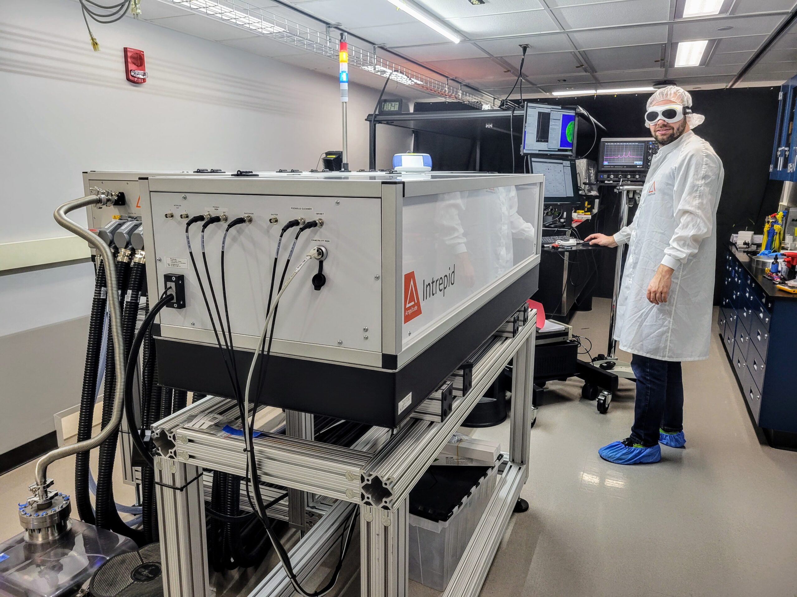
The installation and qualification of the Intrepid – a high energy pulsed laser with a programmable pulsewidth (January 2023).
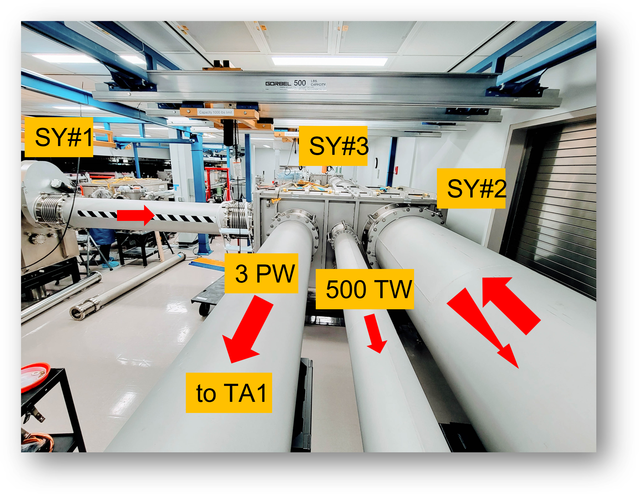
Installation of the 3PW and 500 TW vacuum beamlines (January 2023).
The ZEUS beamlines are completed (April 2023).
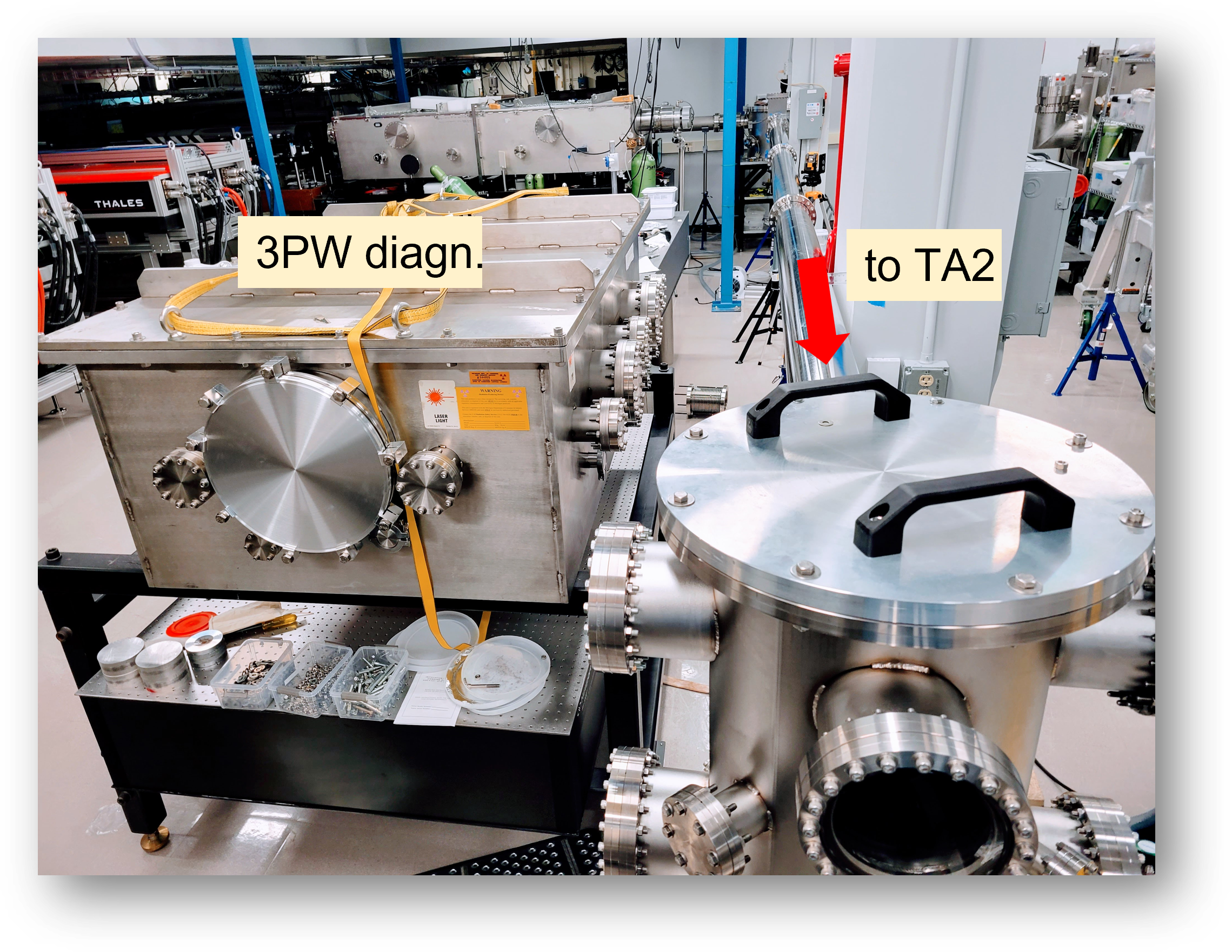
3PW diagnostic chamber and beamline to TA2 installed in a clean room (April 2023).
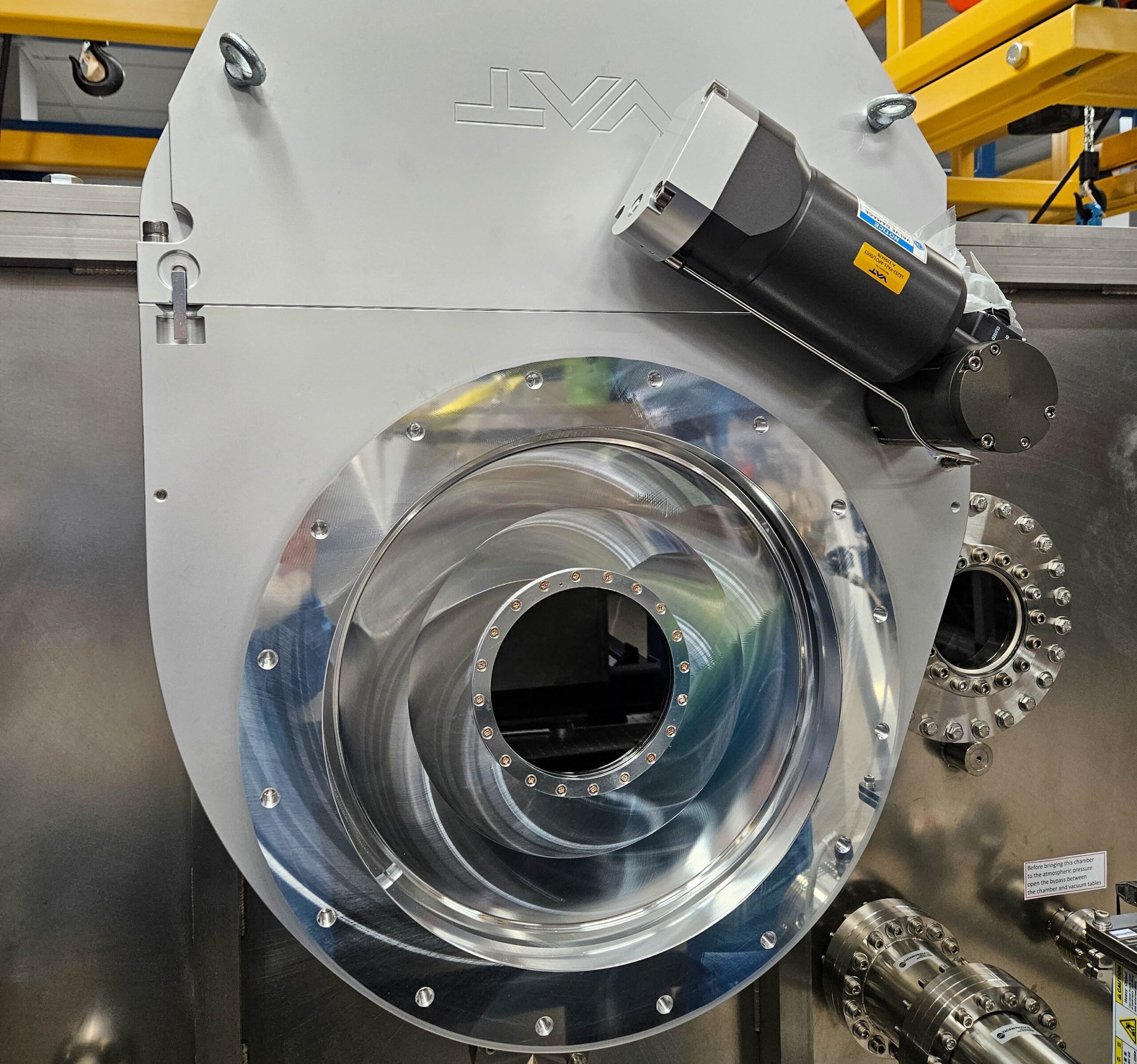
ISO400 VAT pendulum valve with a 6 inch sapphire window (May 2023).
3PW compressor and a diagnostic chamber (September 2023).
Switch yard #4 and three interaction chambers intalled in Target Area 1 (May 2023).
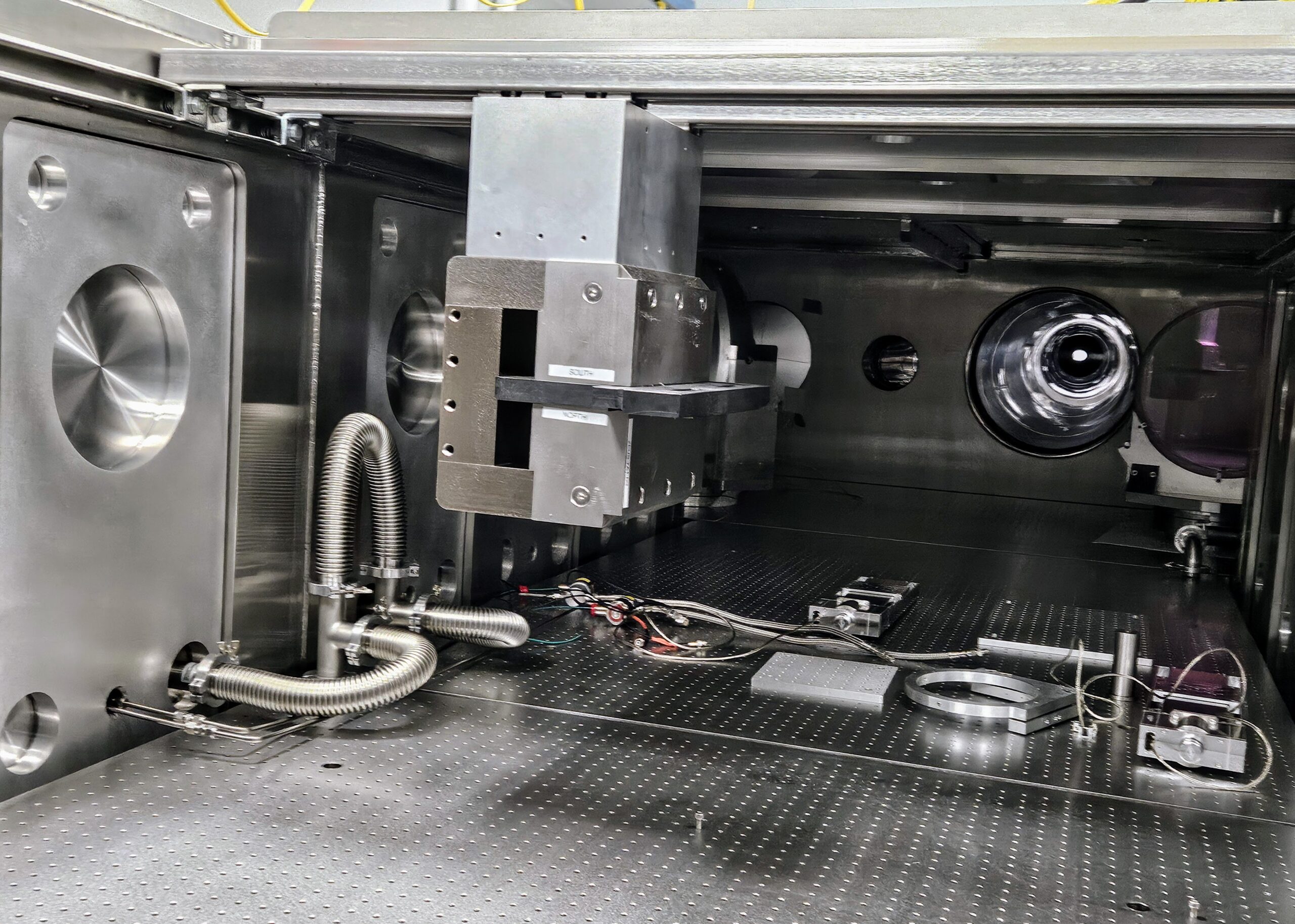
Vacuum optical tables installed in the switch yard #4 (May 2023).
The assembly of the TA1 vacuum chambers is completed (June 2023).
The assembly of the TA1 vacuum chambers is completed (June 2023).
Local radiation shielding and electron beam dump installed in Target Area 1 (August 2023).
A 3PW mounted compressor grating (October 2023).
An alignment of a 3PW compressor (February 2024).
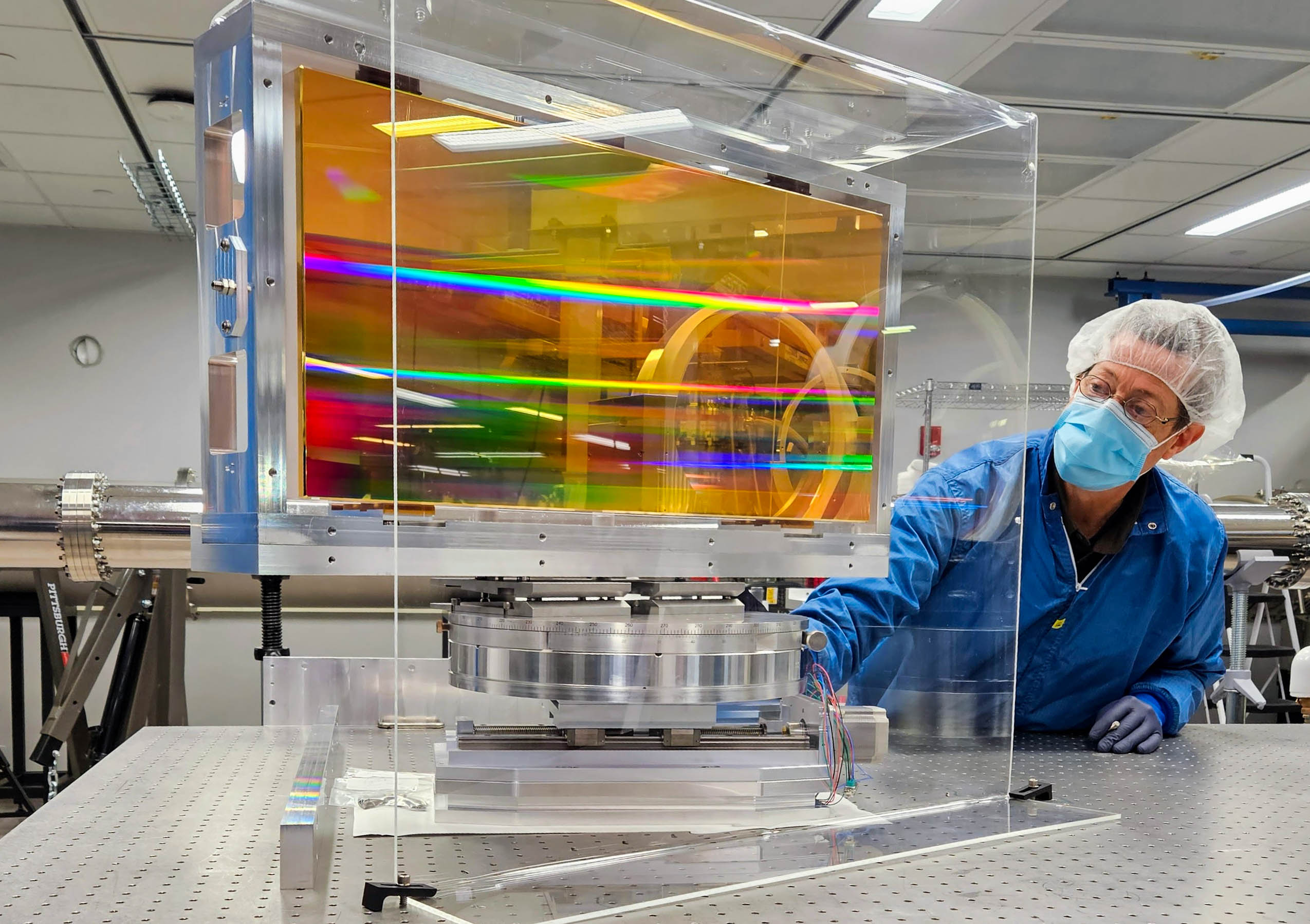
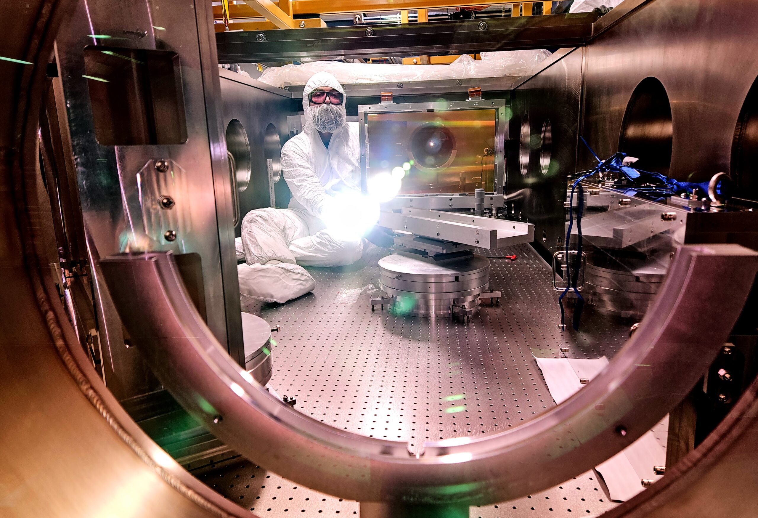
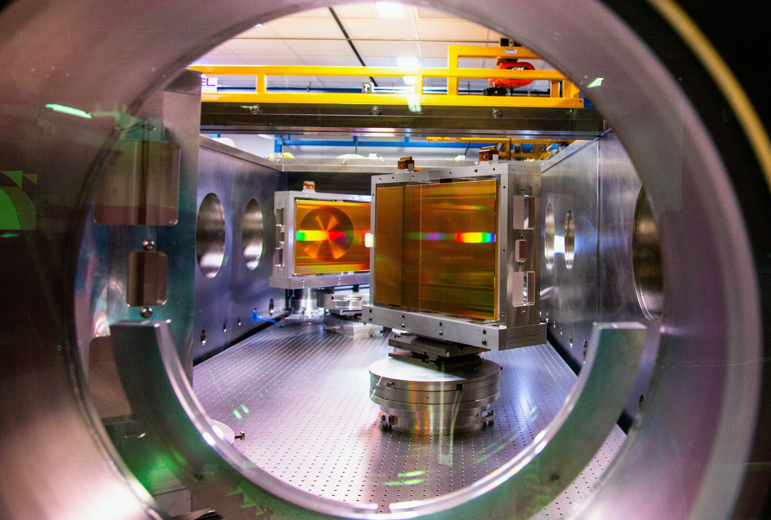
Installation and alignment of the large size diffraction gratings into 3PW compressor is completed (March 2024).
Installation of a 20″ transport mirror into switch yard #2 (March 2024).
An assembled low profile 20inch diameter mirror mount (April 2024).
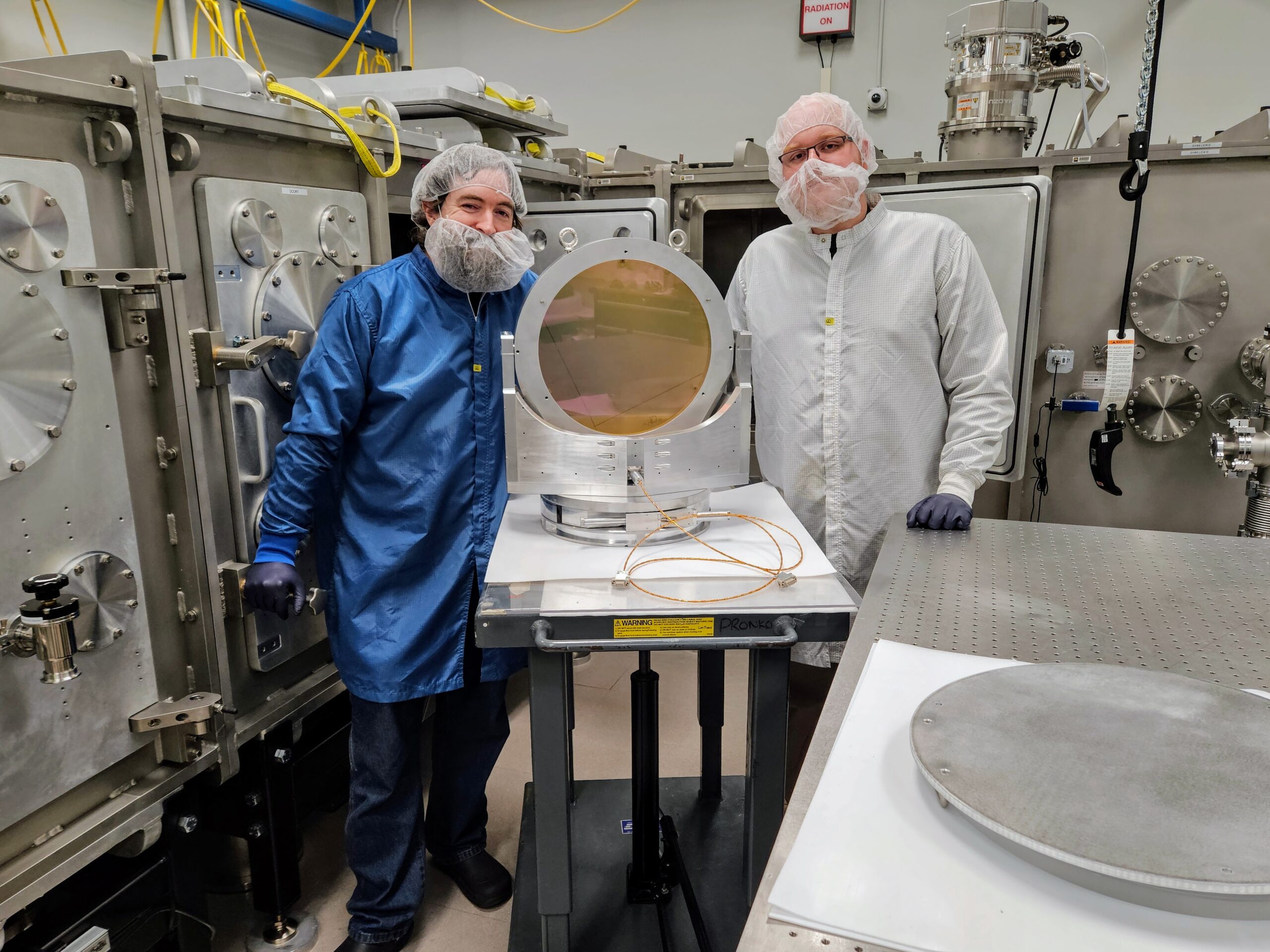
A 1 Tesla dipole magnets for electron spectrometer installed in TA1 chamber (April 2024).
An assembled 20 meters focal length focusing optics (April 2024).
A 35 cm diameter long focal length (f~20 meters) focusing optics installed in a switch yard #3 (April 2024).
A 12 inch diameter adaptive optics installed in a switch yard #4 (April 2024).
Large size transport optics and deformable mirror in SY#4 (April 2024).
Radiation Shielding
Prof. Igor Jovanovic has led the design of radiation shielding for the new ZEUS target areas using FLUKA and Geant4 codes.
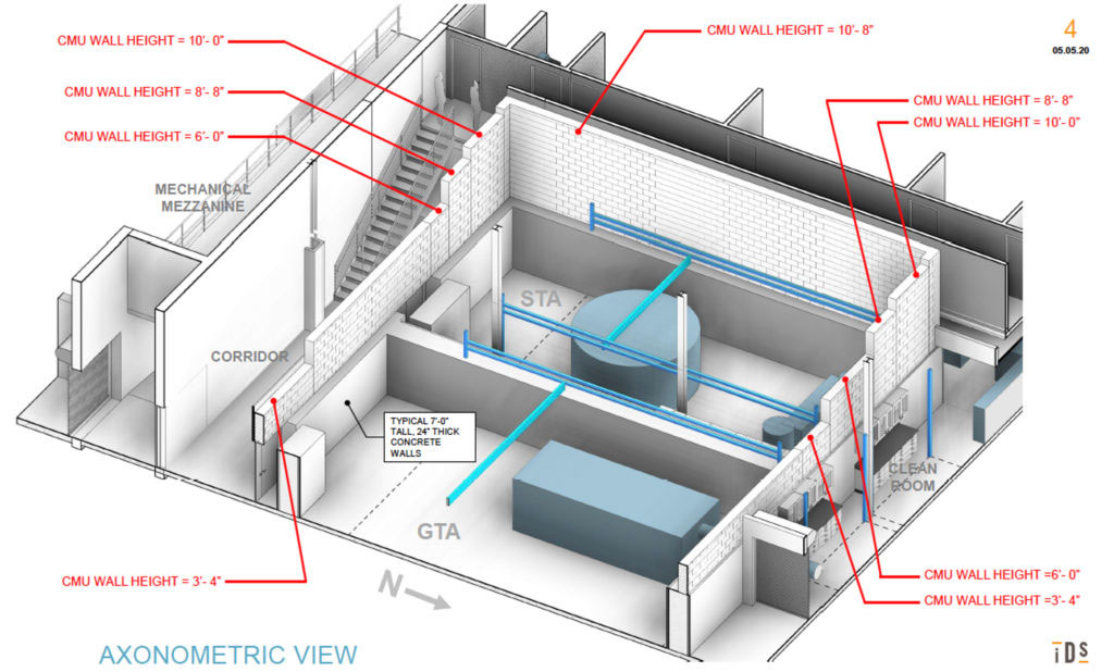
All radiation-generating facilities have a legal obligation to protect their personnel from ionizing radiation. Each facility has different requirements that must be addressed by the shielding, so specific designs need to be developed and ultimately implemented. For GeV-level accelerators, several meters of radiation shielding or a beam dump combined with radiation shielding are required to reduce the radiation dose to a safe level. We developed a facility design suited for shielding of the gas target area in ZEUS, which includes an electron beam dump. The overall design goal is to limit the hourly dose to 0.02 mSv/h (2 mrem/h) and the annual dose to 1 mSv/year (100 mrem/year), according to the radiation safety regulations. The facility design is illustrated in Fig. 1, which does not display the local shielding (beam dump).
Figure 1: The overall facility radiation shielding design.
Simulations
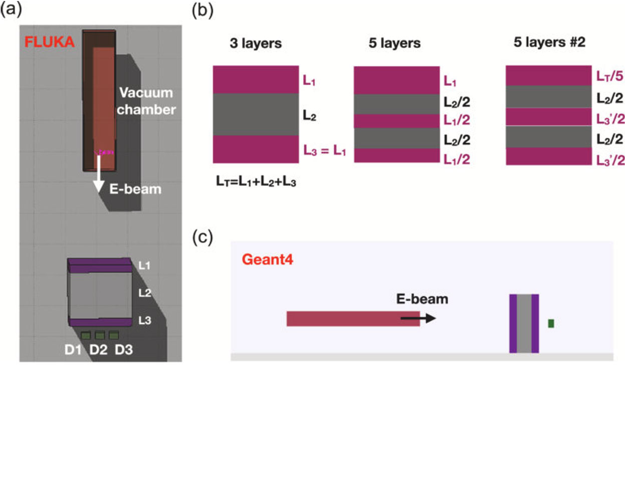
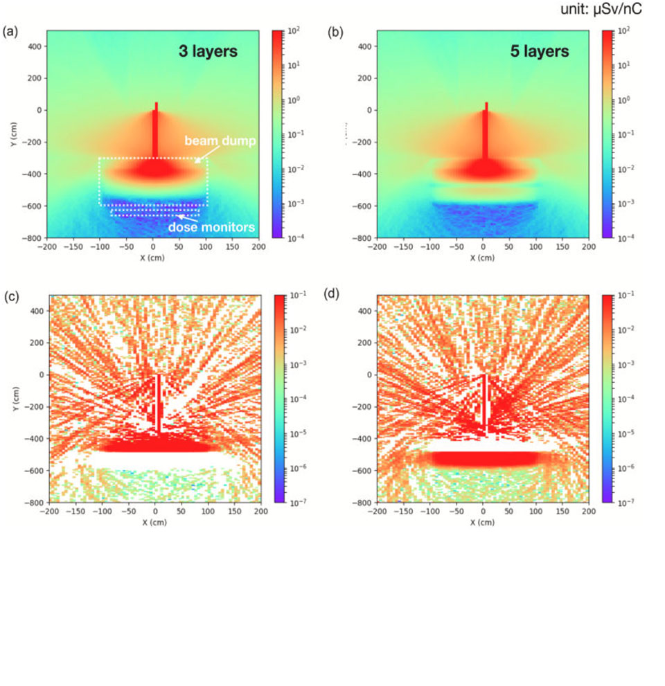
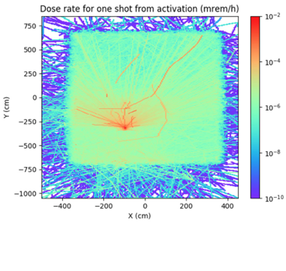
We conducted Monte Carlo simulations using FLUKA and validated them in Geant4. An additional validation was performed with the design of similar facility. The simulation geometry is shown in Fig. 2 and includes the optimization of the composition, thickness, and width of stacked layers of the beam dump. Representative results for the prompt dose are shown in Fig. 3. Also important to the facility design is the longer-term activation, for which the simulation was also carried out (Fig. 4).
Figure 2: (a) Simulation geometry (top view) in the Monte Carlo code FLUKA. (b) Different stacking methods are used to test the effectiveness of the radiation shielding. (c) The same simulation geometry (side view) is also defined in the Geant4 for comparison.
Figure 3: Comparison of the ambient dose equivalent between the (a) three-layer and (b) five-layer stacking configuration with the HD concrete and iron stacking. The difference between the two configurations is shown in (c) and (d).
Figure 4: Example simulation of the activation in ZEUS gas target area.
Solid Target Area Shielding Design
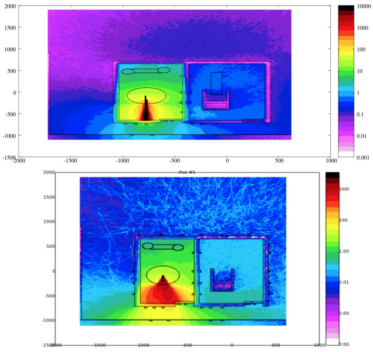
The solid target area is another major experimental area of ZEUS for which the shielding design is necessary. Preliminary designs have been developed to address the challenging environment of higher beam divergence than in the gas target area and the multi-particle environment that requires a combination of shielding materials and geometries. Preliminary FLUKA modeling is illustrated in Fig. 5.

 MENU
MENU